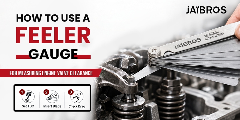
Correct engine valve clearance is important for smooth engine operation, reliable performance, and proper valve timing. The clearance between the valve and its operating mechanism allows components to expand as the engine heats up. If this gap is too small or too large, it can affect engine performance and may cause mechanical problems.
A feeler gauge is a simple measuring tool used to check small gaps between two surfaces. It contains thin metal blades of different thicknesses that can be inserted between engine components to check whether the clearance matches the manufacturer's specifications.
Understanding the measurement process, selecting the correct blade, and following the recommended engine service procedure can help mechanics and technicians perform accurate inspections.
What Is Engine Valve Clearance?
Engine valve clearance is the small gap between the valve mechanism components when the valve is fully closed and the engine is positioned according to the manufacturer's inspection procedure.
The exact location of the measurement depends on the engine design. In some engines, clearance is checked between the rocker arm and valve stem. In others, it is measured between a cam lobe and a tappet or another specified component.
This gap is necessary because engine components expand when heated. Incorrect clearance can affect how valves open and close.
Excessive clearance: May produce ticking or tapping noises and can affect valve lift and timing.
Insufficient clearance: May prevent a valve from closing completely when the engine becomes hot, potentially causing compression loss and valve damage.
Correct clearance: Helps maintain the intended valve operation and supports reliable engine performance.
Always refer to the service manual for the correct clearance value and inspection conditions.
Tools Required for Measuring Valve Clearance
Before starting the inspection, prepare the following tools:
A suitable thickness-measuring blade set
The correct spanner or socket for engine covers and fasteners
A ratchet or suitable tool for rotating the crankshaft
The manufacturer's engine service manual
Cleaning cloths and appropriate safety equipment
Ensure the engine is switched off and has cooled to the temperature specified in the service manual. Many engines require cold measurement, while some procedures specify different conditions.
Disconnect the battery if required by the manufacturer's instructions. Keep loose clothing and fingers away from moving components, and never perform this inspection with the engine running.
Step-by-Step Guide to Measuring Engine Valve Clearance
Step 1: Check the Manufacturer's Specifications
Start by finding the recommended intake and exhaust valve clearances in the service manual. These values may differ, even within the same engine.
The manual should also explain whether measurements must be taken with the engine cold or warm and how the crankshaft should be positioned.
Never assume that one clearance value is suitable for every vehicle or engine.
Step 2: Access the Valve Mechanism
Remove the necessary engine cover or valve cover according to the service instructions. Clean the surrounding area before opening the engine to prevent dust, dirt, and debris from entering.
Identify the valve mechanism and the specified measurement points. Make sure the components are accessible and clean before inserting a blade.
Step 3: Position the Engine Correctly
Rotate the crankshaft using the recommended method until the relevant cylinder reaches the specified position, commonly top dead centre on the compression stroke for many conventional engines.
At this point, the relevant valves should be in the required closed position. Follow the engine-specific procedure because valve arrangements and inspection positions vary.
Step 4: Select the Correct Blade Thickness
Choose a blade that matches the specified clearance or the closest appropriate thickness for checking the gap.
For example, if the service manual specifies a clearance of 0.20 mm, select a 0.20 mm blade if available. Insert it gently between the specified contact surfaces.
The blade should move with a slight, consistent drag. It should not require excessive force, bend during insertion, or move completely without resistance when the procedure expects a close fit.
Step 5: Check the Clearance
Move the blade carefully through the gap without forcing it. Compare the resistance with the manufacturer's inspection guidance.
If the blade is too tight, try the next thinner size. If it moves too freely, try the next thicker size where appropriate.
Record the measurement for each valve separately. This makes it easier to identify variations between intake and exhaust valves and determine whether adjustment is necessary.
Step 6: Adjust and Recheck if Required
If the measured clearance is outside the specified range, follow the manufacturer's adjustment procedure. Depending on the engine, this may involve an adjustment screw, locknut, or selecting a different shim thickness.
After adjustment, tighten all fasteners to the specified torque and measure the clearance again. Rotate the engine as directed and repeat the check if required.
Finally, reinstall the covers and related components correctly before starting the engine.
Understanding Blade Sizes, Least Count, and Measurement Range
Three important specifications help users choose the right measuring tool.
Blade Sizes
The available blade thicknesses determine which gaps can be checked directly. A metric set may include sizes such as 0.05 mm, 0.10 mm, 0.15 mm, 0.20 mm, and other increments.
Choose a set that covers the clearances specified for the engine you maintain.
Least Count
The least count is the smallest marked measurement increment available in the set. For example, if consecutive blade sizes differ by 0.05 mm, that increment represents the available size step between those blades. It does not automatically guarantee measurement accuracy of 0.05 mm.
Measurement Range
The measurement range describes the smallest and largest blade thicknesses included in the set. A range from 0.03 mm to 1.0 mm can be useful for checking different small gaps, provided the required clearance falls within the available sizes.
For reference, the 26-blade metric measuring set lists blade thicknesses from 0.03 mm to 1.0 mm. Always confirm that the available increments suit the engine's specified clearance.
Common Mistakes to Avoid
Incorrect measuring practices can lead to inaccurate readings and unnecessary adjustments. Avoid these common mistakes:
Measuring at the wrong crankshaft position.
Ignoring the manufacturer's temperature requirements.
Forcing a blade into a narrow gap.
Using bent, rusty, dirty, or damaged blades.
Confusing intake and exhaust clearance specifications.
Adjusting the valve without checking the measurement again.
Tightening fasteners without following the specified torque.
Keep the blades clean and dry after use. Apply suitable rust protection when necessary, and store them properly to prevent bending and corrosion.
Conclusion
Accurate engine valve clearance measurement depends on correct engine positioning, clean contact surfaces, suitable blade selection, and careful interpretation of the reading. Following the manufacturer's specifications helps prevent incorrect adjustments and supports reliable engine operation.
Regular inspection, proper tool handling, and rechecking after any adjustment can help mechanics maintain consistent results and identify valve clearance problems before they develop into more serious mechanical issues.For reliable precision tools and workshop essentials, explore Jaibros to find suitable products for your measurement and maintenance needs.
Frequently Asked Questions
1. What is a feeler gauge used for in engine maintenance?
A feeler gauge is used to measure small gaps between two components. During engine maintenance, it helps technicians check valve clearance against the manufacturer's specifications. It can also be used for other applications requiring clearance checks, such as inspecting certain mechanical assemblies. The correct blade thickness and measurement procedure are essential for obtaining a useful reading.
2. What is the least count of a feeler gauge?
The least count depends on the smallest measurement increment provided by the blades in the set. For example, if the available thicknesses increase in steps of 0.05 mm, that is the smallest marked increment between those sizes. However, the actual measurement accuracy also depends on blade condition, handling, surface cleanliness, and the method used to check the clearance.
3. How do I choose the right feeler gauge set?
Choose a feeler gauge set based on the required measurement range, available blade increments, and the application. For engine valve maintenance, check the service manual first to identify the specified clearance values. Ensure the set contains suitable blade thicknesses for those measurements. Blade material, clear markings, and good storage protection are also useful considerations for regular workshop use.
4. What does the range of a feeler gauge mean?
The range indicates the minimum and maximum blade thicknesses available in a set. For example, a set ranging from 0.03 mm to 1.0 mm covers blade thicknesses within those limits, subject to its listed increments. The range does not mean every possible thickness is included. Always check the individual blade markings before selecting a size for a specific measurement.
5. Can valve clearance be measured when the engine is hot?
It depends on the engine manufacturer's instructions. Many engines require valve clearance to be checked when cold because temperature changes affect component dimensions. Other engines may specify a particular warm-engine procedure. Always follow the service manual rather than using a universal temperature rule. Measuring under the wrong conditions can produce readings that do not match the specified clearance limits.